The previous article described the basic principles of chirp, both in the case of lasers and external modulators. The following section will present some of the main measurement techniques used to characterize the chirp of optical transmitters, as well as examples of laboratory instrumentation.
Chirp measurement techniques.
Several methods exist for characterizing the chirp of optical transmitters in the laboratory. For time-domain measurements, the laser must be modulated with the same data pattern that will be used in the real system. Additionally, a synchronization or trigger signal is required. The available measurement techniques are described below.
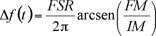
Power discriminator method.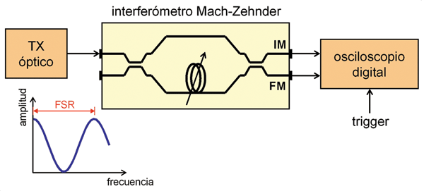 As shown in Figure 1, this technique uses a Mach-Zehnder interferometer as a frequency discriminator. This device achieves FM-IM conversion, which then allows for the measurement of frequency modulation, or chirp, using a digital oscilloscope. The differential delay between the two paths causes a sinusoidal amplitude response to frequency variations. The period of this response is known as the FSR (free spectral range). The variable delay must be adjusted so that the laser's nominal frequency lies within the rise and fall intervals of the sinusoidal function. Thus, from the sum (FM) and difference (IM) terms at the interferometer output, the chirp can be calculated using:
 Optionally, the Mach-Zehnder interferometer can be replaced by a birefringent fiber-based scheme to achieve a differential delay between the main polarization states.
Optical gate method.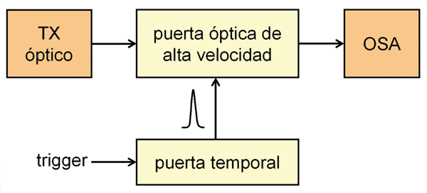 The principle behind this measurement technique is simple, although its practical implementation is complex. The laboratory setup is shown in Figure 2. An optical gate captures a specific time interval while simultaneously performing a frequency sweep on an optical spectrum analyzer (OSA). Then, from the power data as a function of frequency and time, the chirp of the input signal can be estimated using the following formula:
 The optical gate is shifted slightly in time, and the process is repeated until all the data in Table I have been captured. The temporal resolution of the measurement depends on the width of the optical gate's control pulse, as well as its accuracy in temporal positioning. On the other hand, the repeatability of the OSA's frequency sweep and its amplitude accuracy determine the frequency and power resolution, respectively. One of the main drawbacks of this method is that it typically consumes considerable computation time, since an OSA sweep is required for each time sample. Additionally, to perform measurements over large time intervals with good resolution, extinction ratios for the optical gate greater than 50 dB are required.
Monochromator Method.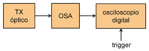 Another technique commonly used to measure chirp is shown in Figure 3, which employs an optical sensor array (OSA) (with fiber optic output) and an oscilloscope. In this case, frequency processing precedes time processing, although the operating principle is very similar to the previous technique. The OSA locates the signal to be measured and determines the list of wavelengths by means of a sweep. Subsequently, the OSA filter is sequentially scanned over each of these wavelengths, where the oscilloscope captures a time trace. Finally, the captured data are corrected to compensate for the possible dispersion of the optical filter and entered in columns in Table I. Figure 4 schematically represents a possible measurement setup.
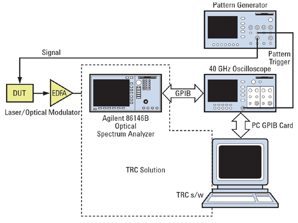 The main advantages of this measurement technique are summarized below. Firstly, it exhibits a low dependence on the polarization of the input signal, which gives it high repeatability. Secondly, it allows measurement of WDM signals. Additionally, the use of an EDFA at the OSA input makes it possible to measure signals at levels as low as -35 dBm, since the monochromator filters eliminate much of the ASE noise.
Laboratory Instruments.
In reality, the number of commercially available chirp measurement devices is rather limited. This may be because they are designed for very specific purposes, and alternative methods exist that 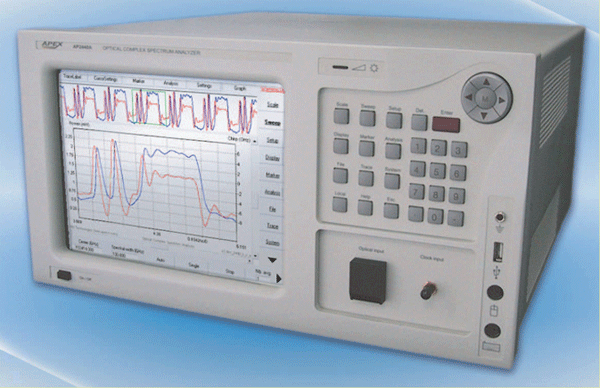 utilize general-purpose instrumentation, as discussed earlier (Figure 4). Nevertheless, some options are available.
Among them is the AP2440A from APEX Technologies (Figure 5), which is notable for its ability to perform chirp measurements up to 640 Gbit/s. This is a complex spectrum analyzer capable of directly measuring the optical phase. The analysis is based on sampling the field spectrum, capturing phase and amplitude information for the chirp signal.
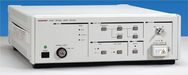
Finally, another example of equipment is the Advantest Q7607, which is shown in Figure 6.
Francisco Ramos Pascual. PhD in Telecommunications Engineering.
Full Professor at the Polytechnic University of Valencia.